In the past it was a hassle to get off of my motorcycle to key in the garage door code before getting back on the cycle to pull it into the garage. Stashing a garage door opener in my jacket pocket was a little better but I still had to stop to take off my motorcycle gloves. My solution was to hack a garage door opener to activate via a switch on my handle bar. Because I do almost all of my riding in the city, I never use my passing switch so this was the one I chose to tap into. The following is a guide of how I did it and was done for a LiftMaster opener/remote. The same concepts should apply to other brands but I have not tried them.
Materials
- A LiftMaster garage door remote. Make sure you get the correct remote for your opener (based on whether the learn button on your opener is red-orange
or purple
). I used the remote with only one button to keep things simple.
- A TO-92 (3 pin through hole) NPN transistor. I bought a pack of these from RadioShack. The specific one I used is KSP2222A but there are many equivalent part numbers that will work.
- A 2.7M Ohm 1/4 watt resistor. If you can’t find this exact one, any resistor near this value should work. I bought a huge variety pack of resistors that included this one on eBay for only a few bucks.
- Red and black small gauge stranded wire
- A wiretap connector
to tap into your motorcycle’s switch
Tools
- Soldering iron
- Flush/diagonal cutter for trimming the transistor leads
- Solder sucker or copper braid to remove the solder from the remote’s button
- Something to notch the side of the remote. A dremel tool works well for this.
Step 1: Remove the Push Button Switch
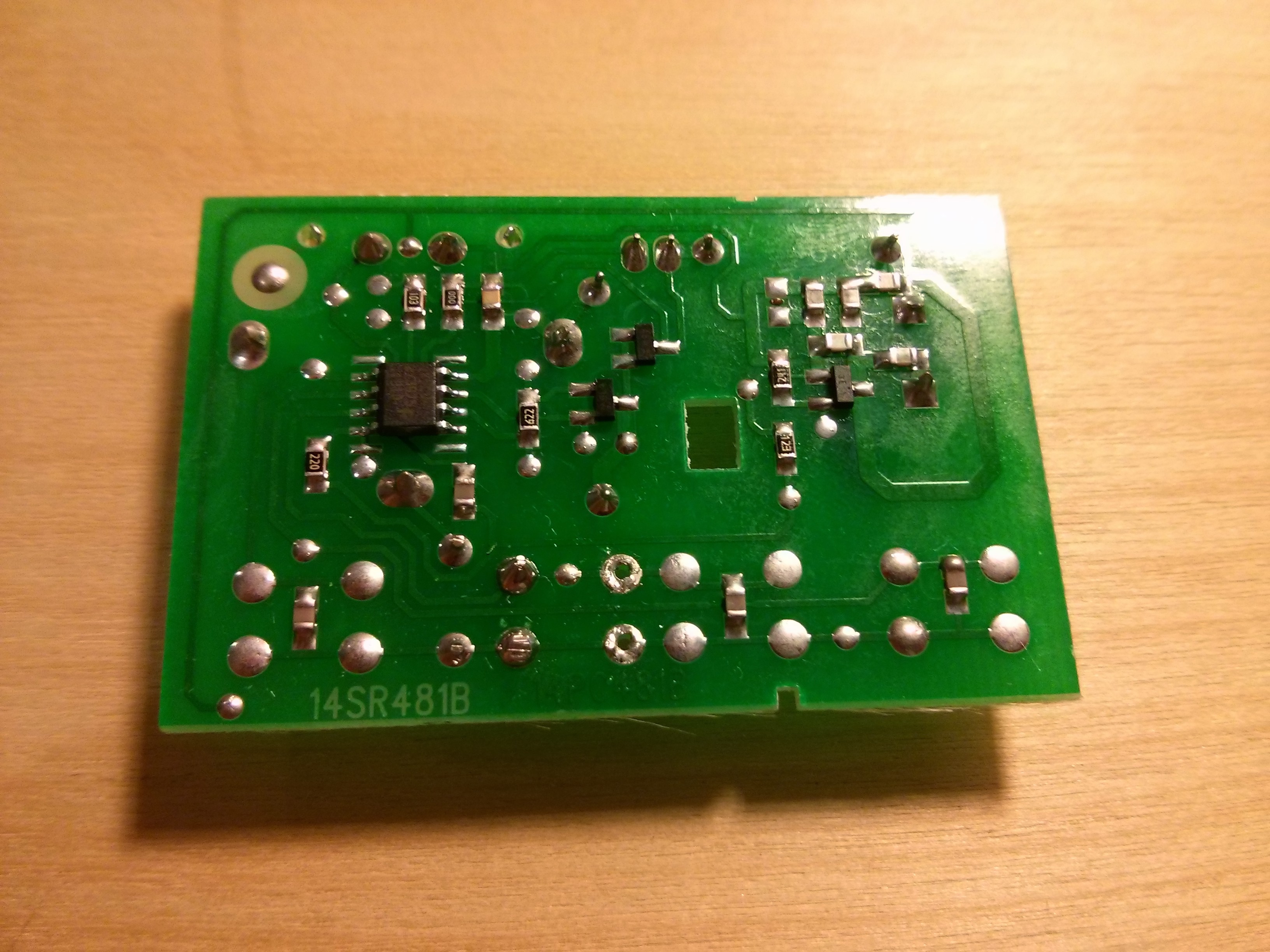
If you haven’t already, don’t program your remote for your opener yet. You don’t want to accidentally be opening and closing your garage door while working on this project. Begin by opening up the case of your remote and removing the circuit board.
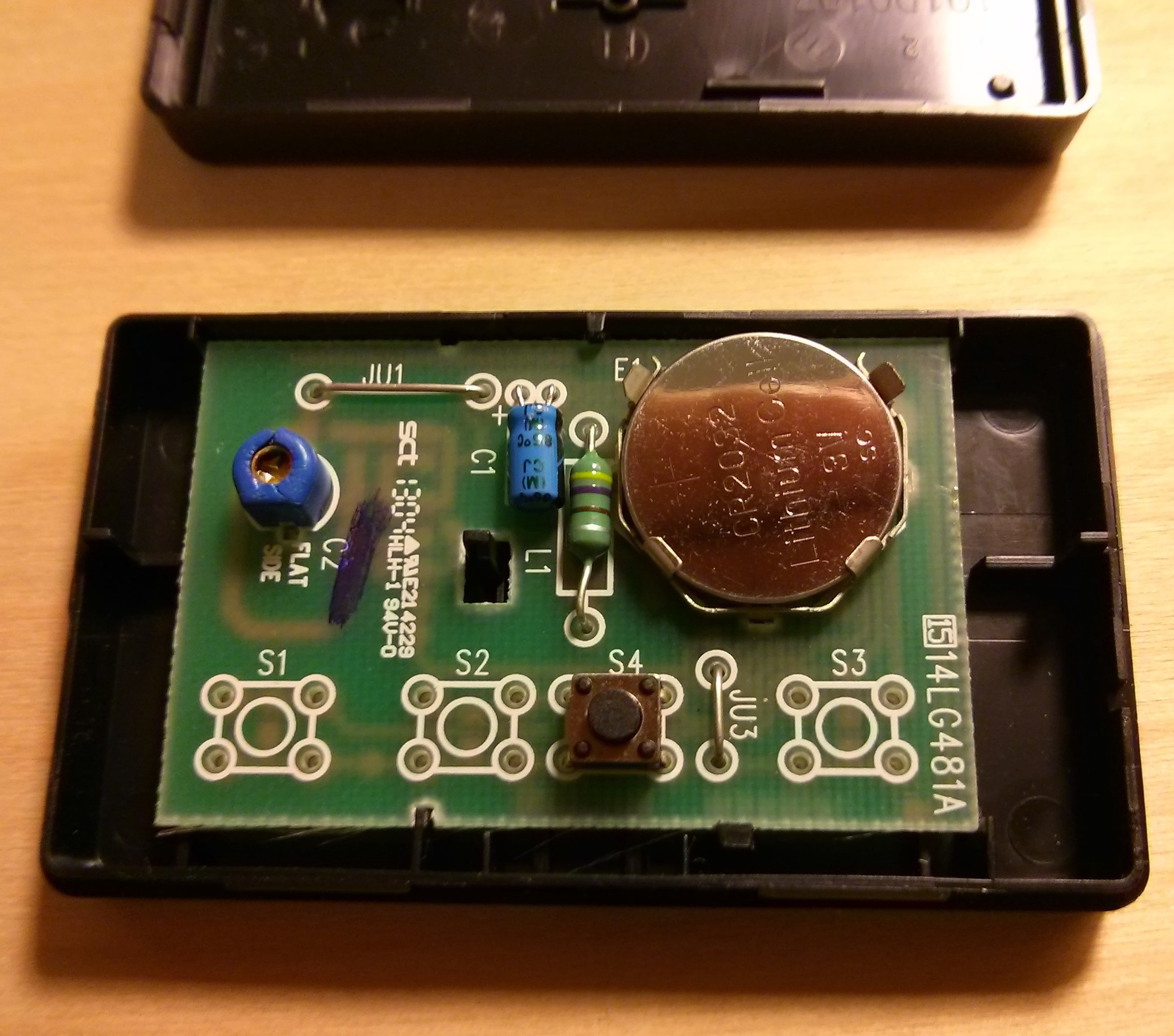
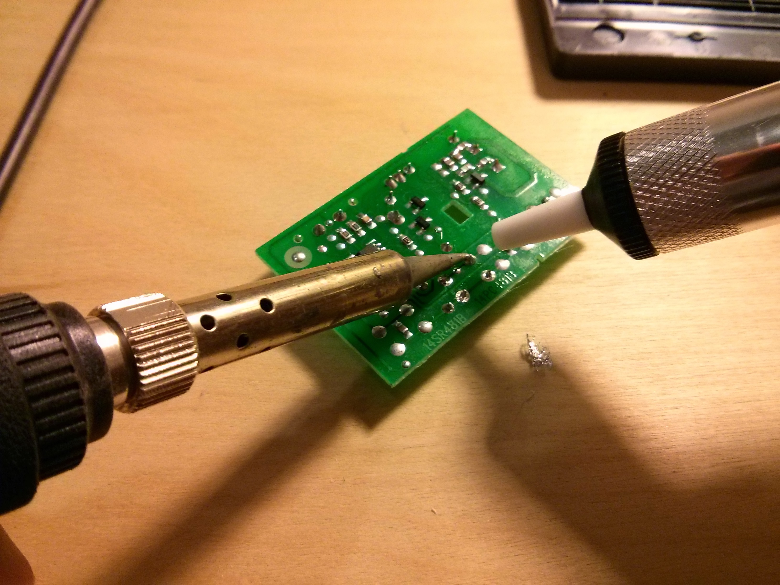
You’ll see a small black and silver momentary push button switch near the bottom. Pressing down on this switch completes a circuit which activates the opener. We want to remove the switch so that we can replace it with a transistor activated by a 12V signal from the bike. Use your soldering iron and solder sucker or copper braid to remove the solder from the pins of the button.
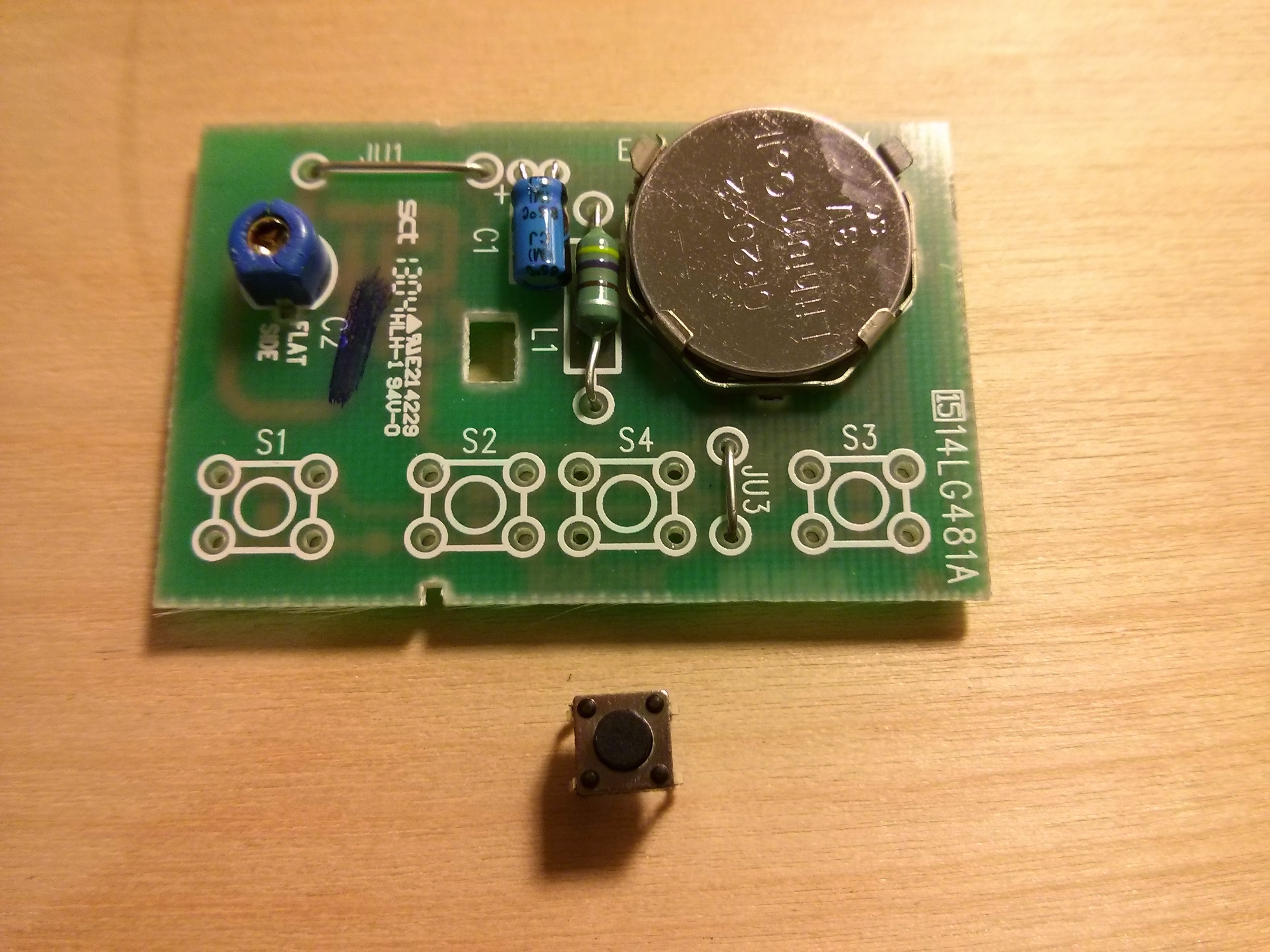
After the solder is removed, the button will easily come off of the board.
Step 2: Solder the transistor
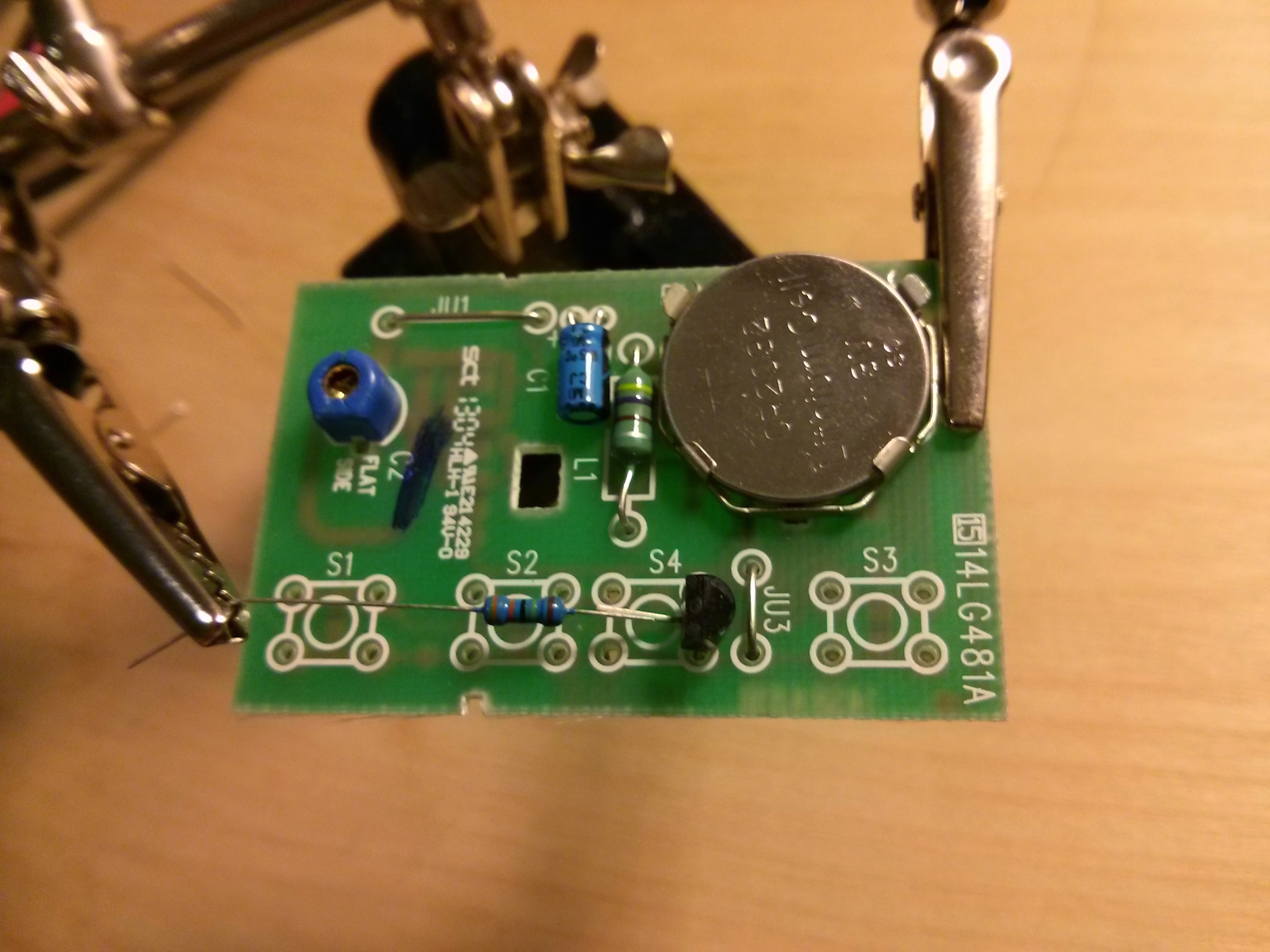
Next we need to replace the button with the transistor. The transistor acts as an electronic switch. When the base of the transistor is activated by the 12 volts from the motorcycle, it will allow current to flow from the collector to the emitter. Bend up the middle lead of the transistor and insert the other two leads into the circuit board. Make sure it matches the orientation shown in the photo.
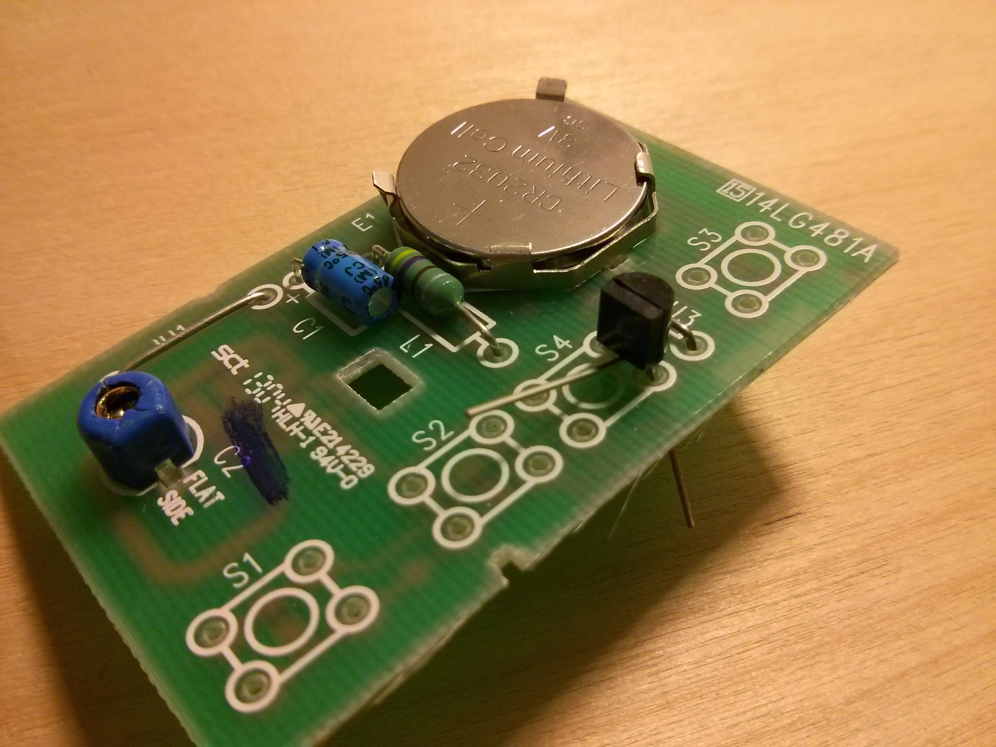
Then solder and trim the leads on the reverse side of the board.
Step 3: Add the Resistor
Only a very small current is needed for the remote’s circuit to consider our new switch “closed.” We’re going to solder a resistor to the base of the transistor to make sure we don’t damage it when we send it 12 volts from the motorcycle. Clip the leads short on the resistor and solder it to the remaining transistor lead.
Step 4: Solder signal and ground wires
Cut a couple feet of red and black wire and strip the ends. Solder one end of the red wire to the end of the resistor. Solder one end of the black wire to the circuit board as shown.

Step 5: Modify the case
You’ll need to cut a couple notches into the garage door opener’s case where the wires will come out. I believe I used a dremel tool for this. When you’re done, thread the wires through the notches, and snap the circuit board back into its case.

Step 6: Program and test the remote
For this step you need access to a 12 volt power source–the terminals of your motorcycle’s battery will work in a pinch. To program the remote, tap the orange or purple learn button on your opener then hold the red wire to the positive terminal on the battery and the black wire to the negative terminal for a few seconds. Your garage door light should blink when the programming is complete.
Now disconnect the remote then connect it once more. If your garage door activates, it’s working!
Step 7: Install opener on motorcycle
This is where you get to be a bit creative. I chose to tap the red signal wire into the high beam wire on my SV650, allowing me to use my passing signal to trigger the garage door opener. To do this, I made a small cut to get into the wire bundle near my steering column then used the posi-tap connector to make the connection. I then wrapped the bundle back up with electrical tape. You can either connect the ground to a ground wire on your motorcycle or to any metal part of the frame. I chose to screw it down using the screws holding down my gas tank.
Finally, you’ll need a place to stash the remote. On my SV650, I found that there was extra space underneath my gas tank in front of the airbox.
I forgot to take pictures of this step but if you think it’d be helpful let me know and I’ll post some. Have fun and enjoy your motorcycle’s new garage door opening abilities!
No Comments