We’re going to use the Raspberry Pi’s SPI bus to control Microchip’s MCP4151 8-bit digital potentiometer. The MCP4151 is an 8 pin SPI device that can be used to programmatically control output voltage. The GPIO pins on the pi run at 3.3 volts meaning that we can command the pot to output between 0 and 3.3 volts. However, if we instead power the pot with 5 volts then we can control a voltage between 0 and 5 volts. Note that PWM is a possible alternative to a digital pot that doesn’t require an extra chip. However, this can add noise to the signal that wasn’t acceptable for my project.
Microchip’s datasheet is recommended reading before starting this project.
Parts List
- Raspberry Pi
- Breadboard
- A Pi Cobbler Breakout
- Microchip MCP4151 digital potentiometer
- A 0.1uF capacitor
- An LED
- A 330 ohm resistor
Step 1: Configure SPI on the Raspberry Pi
Follow the first two steps in Controlling an SPI device with the Raspberry Pi.
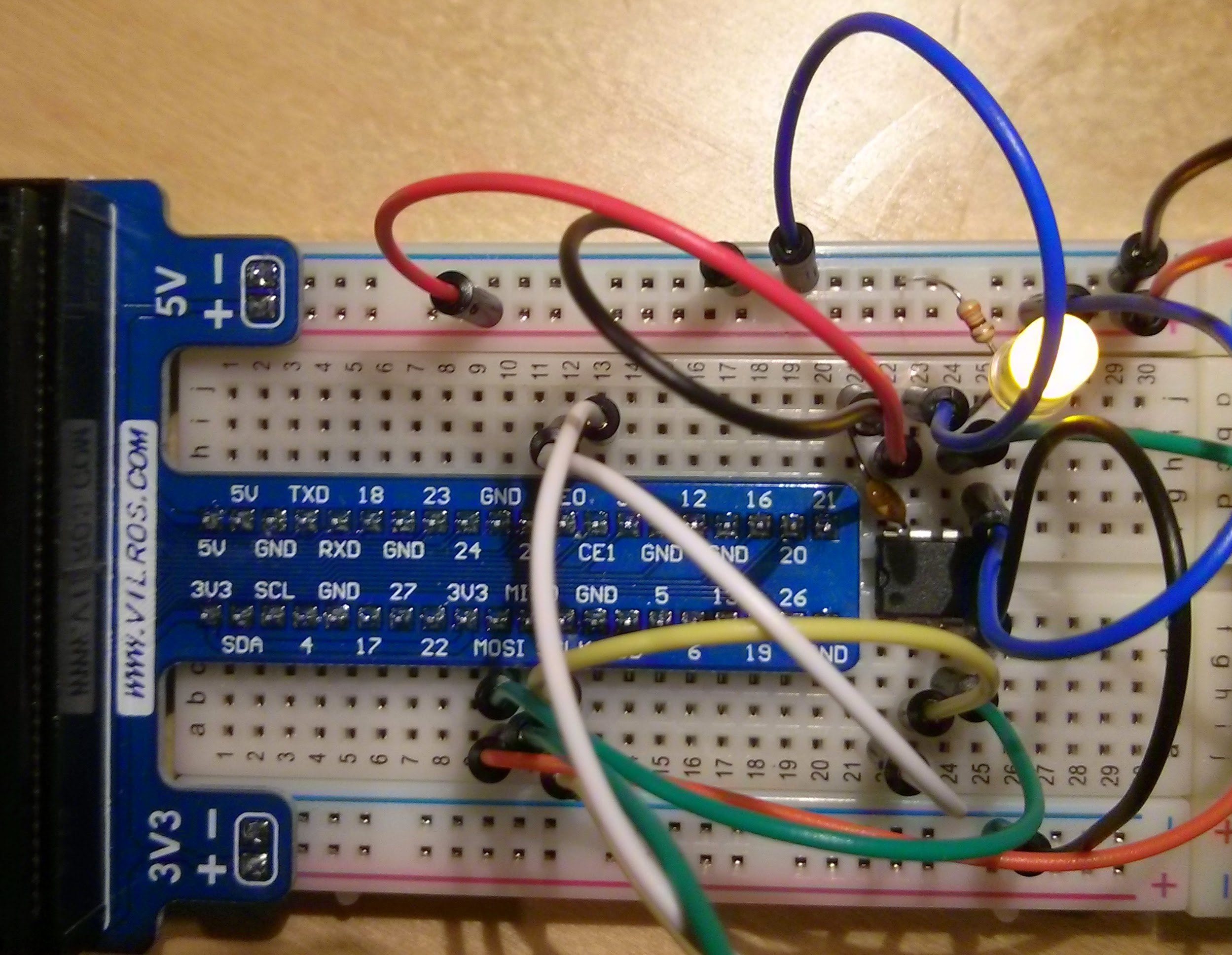
Step 2: Wire up the components
Being a pin-limited device, the SPI input and output on the MCP4151 shares one pin. That’s not a problem in our case since we’re only interested in writing to the device.
You’ll notice that we’re powering the pot with 5 volts despite the Raspberry Pi being a 3.3 volt device. This is fine because 1) The Pi sends commands to the pot but receives nothing back. Therefore, there is no risk of overvoltage on the Pi’s pins. And 2) The pot recognizes any SPI input over 0.7 volts as a high signal. This means the 3.3 volts from the Pi is plenty to communicate with the pot.
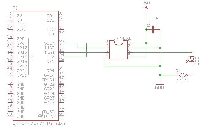
As you can see, the power, ground and the SPI signals take up most of the pins. The actual potentiometer terminals are pins 5, 6 and 7.
| Pin | Description |
|---|---|
| 1 | SPI chip select input |
| 2 | SPI clock input |
| 3 | SPI serial data input/output |
| 4 | Ground |
| 5 | Potentiometer terminal A |
| 6 | Potentiometer wiper terminal |
| 7 | Potentiometer terminal B |
| 8 | Positive power supply input |
Step 3: Create the python script
To test out the device, we’re going to continuously loop through all the possible values for the potentiometer. This will cause the voltage at the wiper terminal grow and shrink between 0 and 5 volts. Create the following script on your Pi.
#!/usr/bin/python
import spidev
import time

spi = spidev.SpiDev()
spi.open(0, 0)
spi.max_speed_hz = 976000

def write_pot(input):
    msb = input >> 8
    lsb = input & 0xFF
    spi.xfer([msb, lsb])

while True:
    for i in range(0x00, 0x1FF, 1):
        write_pot(i)
        time.sleep(.005)
    for i in range(0x1FF, 0x00, -1):
        write_pot(i)
        time.sleep(.005)
Step 4: Run the script
Make the script executable and run it with the following commands.
chmod +x pot-control.py
sudo ./pot-control.py
If all goes well, you should see the LED continuously fade to full brightness then off again.
11 Comments
How would one use a potentiometer to controll resistance? sort of like as a rheostat. I know it can be done but am unsure how to code it.
Hi Takaitra,
What is max A can apply through the IC for to regulate voltage?
Appreciate if you can answer this question.
Many thanks
Best regards,
Hi there
Why are you filling your lsb with input & 0xFF ? I can not see anywhere in the datasheet that you need 1s. Is that your delay? I can not find any good documentation/explanation of the xfer
Hello sir.
I have tried to get my MCP41100 working with your sample, or in general anything I can find about SPI with python on a rpi.. No luck at all. I have tested the chip with arduino, and I have no issue there.
Do you have any tips?
The command byte works differently on the MCP41100 so the code in my example would have to be changed slightly. See page 18 of the datasheet. You said you tested the chip on Arduino and it worked. Can you share the code? Also, are you sure you’ve enabled SPI on your Pi?
Hi, do you know if it is possible to daisy chain the 4151 and control many of them from one spi bus on the pi? I’m looking to control each 4151 independently. For instance if you have a string of rgb leds and you want to control the color of them.
Hi John,
As far as I know it is not possible to daisy chain the MCP4151. You could control a second 4151 with the Raspberry Pi by using the second SPI bus as explained at the end of this post: http://www.takaitra.com/posts/492
A better option would be to use a single chip that has multiple pot outputs. Here is a chart of Microchip’s digital potentiometers: http://www.microchip.com/paramChartSearch/chart.aspx?branchID=11026
You can control multiple devices off of the same SPI bus as the CS lines determine which device is enabled at any one time. You connect all the SDIs together, the SDOs together and the CLKs together. You connect each device’s CS line to a separate CS output. The pi supports two CS lines CS0 and CS1.
You could also feed a CS line in to something line a 74×138 multiplexor and use GPIOs to select the chip you’re going to write to. Connect the G2A enable to the CS on the pi, G2B enable to ground and the G1 enable to VDD. The the GPIOs to A, B and C inputs. Those then select which SPI device you wish to communicate with. The outputs connect to the CS pins on the SPI devices. When the CS line goes low on the Pi the appropriate output line will go low on the demultiplexor taking the CS line low on the device enabling it to be communicated with.
Hi with CS0 and CS1 is good idea. How that would change the code to select the correct chip when writing?
Hi,
Quick novice question: Why is the 1uF capacitor in the circuit? Is it to smooth out the 5V supply since you said your project was noise sensitive? It seems like the circuit would work without it if you just wanted the light to fade in and out.
Thanks for any help!
The small capacitor is known as a bypass or decoupling capacitor. It helps smooth out high frequency noise on the power supply line ensuring that the IC works as intended. The circuit will likely work without it but it’s better to be safe and include it. Sparkfun has a good explanation.