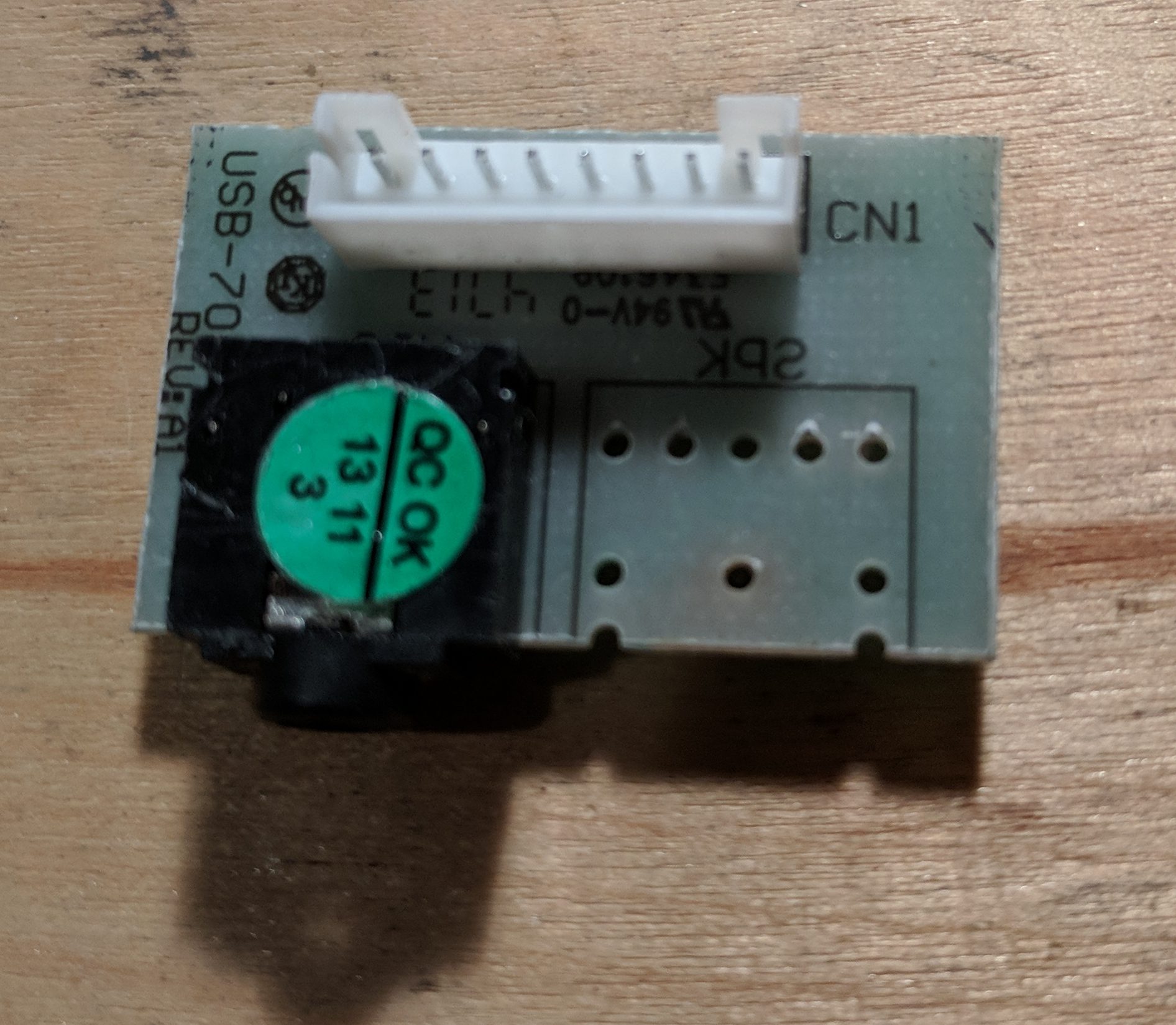
I’ve been using the Fractal Design R4 PC case for a number of years now. I love the design but the placement of the headphone jack leaves something to be desired. It is oriented vertically meaning that pulling on the headphone cable can easily break the port which unfortunately happened to me. Removing the front panel of the case reveals a small circuit board labeled “USB-70A AZALIA REV: A1”.
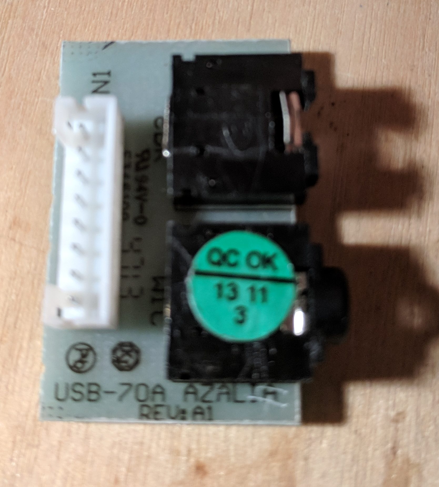
A quick search showed me that it’s not easy to find a replacement for this part so I decided to write up how it can be repaired.
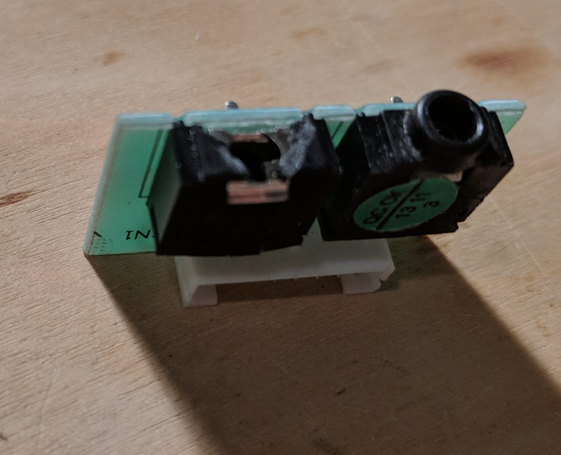
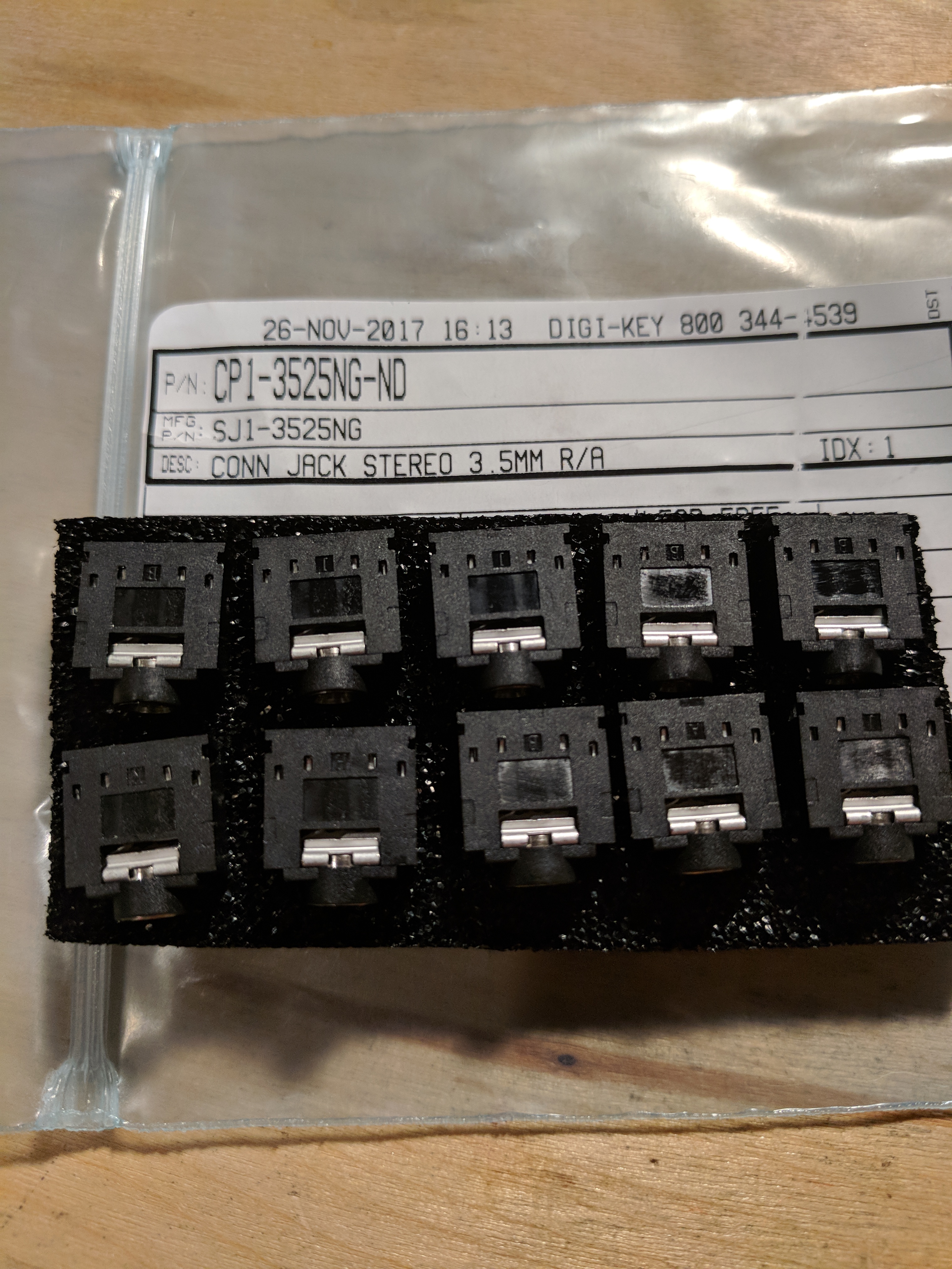
The board consists of two headphone jacks and a pin header. The broken headphone jack needed to be replaced. The first step is finding the correct replacement part. Some searching reveals the CP1-3525NG-ND on Digi-Key. I always order inexpensive parts in multiples of 10 to get the price break and because it’s good to have spare parts around for future projects.
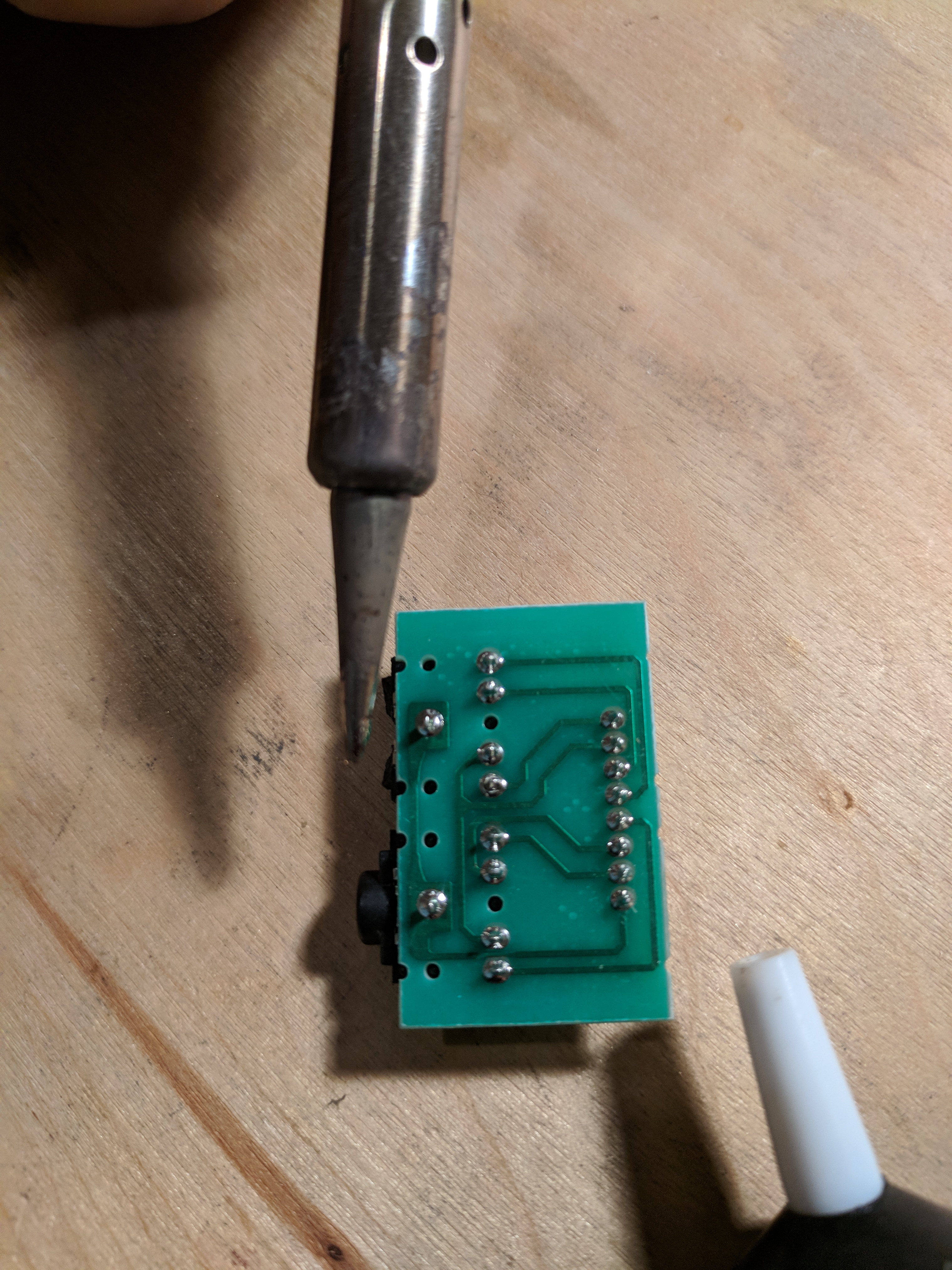
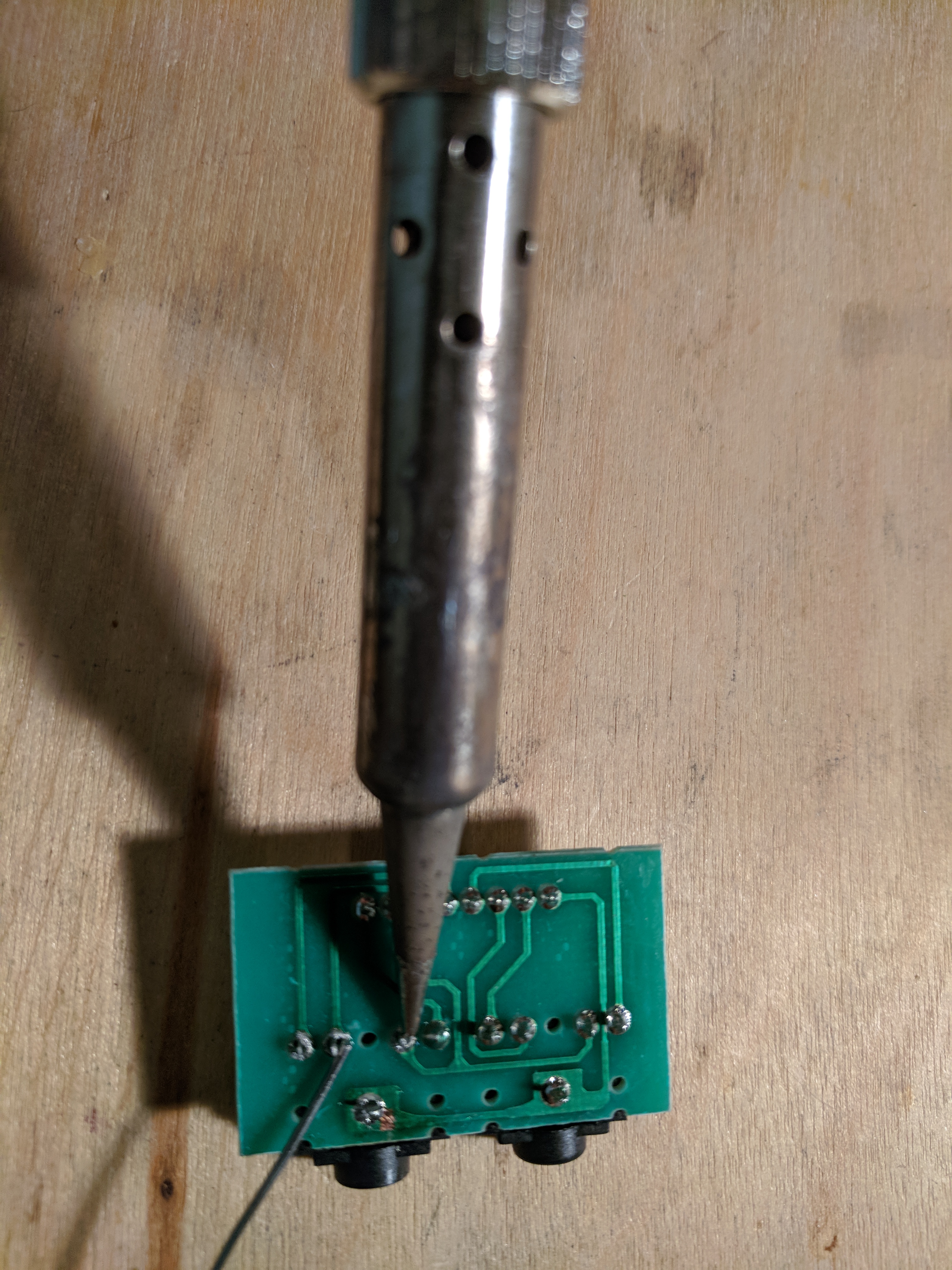
Using a soldering iron, heat up and remove as much of the solder around the pins of the headphone jack as possible. I didn’t have much luck with soldering wick but a soldering vacuum worked well. A trick is to add a small amount of solder to the tip of the soldering iron to help quickly heat the solder in the joint.
After removing the solder, gently remove the old headphone jack.
Solder the replacement headphone jack into place. Heat the pin using the iron and apply enough solder so that it flows into each via.
I ended up replacing both jacks because the replacements have a metal ring that looks more sturdy than the original.

Both my headphones and a microphone worked great after putting everything back together. I was initially worried that the pinout of the replacement jacks might be different than the originals but they turned out to be an exact match.
12 Comments
Hi
So any new developments i also need to fix my mic and audio jack’s on mine define r4?
I finally made it! After soldering 3 wrong types (normally closed) I found the correct one. It is PJ-31080 You normally can only get them in sets of 1.000, but I found a supplier http://www.jingtengele.com/ that sold me a set of 100 – with shipping they costed me 43 USD, but still cheaper than replacing the case.
Another data point: the part recommended in the article (CP1-3525NG-ND) is incorrect, as the “pin sense” bit is not what the motherboard expects; I think it would work for the older PC audio port standard (AC97).
I found the correct ones on AliExpress for 0.53 € https://www.aliexpress.com/item/1005004440992520.html; the same vendor has another listing for black ones that supposedly are the same, but they are not (they are probably the PJ-307, or anyhow they are cabled exactly like the CP1-3525NG-ND). Given the low cost, ultimately I bought pretty much all of them and hoped for the best.
The tricky part is that the most common jacks (such as PJ-307 or CP1-3525NG-ND) are such that
+—[ ]—+
| o 1 |
| |
| |
|o o o o|
+———–+
2 3 4 5
1 is ground, 2 and 5 are L/R (IDK in what order), and 3/4 are short respectively with 2 and 5 when the jack is out, and left floating when the jack is in. A common use of these jacks is putting ground on 3/4, so if an amplifier is connected directly to 2 and 5 you get silence when the jack is not in.
Instead, the correct jacks are such that 3/4 acts as a switch, completely separated from the other pins; when the jack is out, the switch is open; when the jack is in, it is closed.
So, to check if you got the right jack, use a multimeter in buzzer mode, and check:
– jack out: 3 and 4 should be open (no buzz), and should not be connected to any other pin;
– jack in: 3 and 4 should be closed (buzz), and, again, should not be connected to any other pin.
Instead, if you got a wrong one probably 3 is going to buzz with 2 and 4 is going to buzz with 5 when the jack is out, and they are not going to buzz with anything when the jack is in.
Thanks a lot for your explanations
For those looking for additional information, I contacted Fractal support here ( https://support.fractal-design.com/support/tickets/new ) and they answered me in 1 day! and told me that they were sending me the whole panel (free apparently because I provided my postal address) in about a week (I’ll make an edit when recevied)!
I have filled in all the necessary information (serial number and model in particular) for this.
We can therefore say that Fractal responds quickly and well, despite the fact that I ordered the PJ-31080 from Matteo Italia link’s because I did not expect any response for such an old case…
So if you want try asking Fractal directly and if you’re lucky like me they’ll get back to you + send the full piece (expected)
Like you who find yourself here, I’ve done a lot of research and haven’t found a better place to meet on this subject than here. Also, I couldn’t find anywhere a way to order the panel by myself (out of stock or not found).
Then, if i get the correct part, I will become a Fractal shill ahah
Hi everybody,
just received today the complete spare part from Fractal, complete card and associated cable ( https://zupimages.net/up/23/36/12ub.jpg ) pretty cool because the original cable had suffered.
I live in France and it takes a week and a half to arrive, but finally arrive apparently from Sweden
and, by force of circumstances, free because I didn’t pay anything.
I didn’t really believe it because case is quite old but, as indicate above, got response and the replacment part.
I can, ultimately, encourage you to contact Fractal, unless you would prefer to repair it by yourself (which I can understand because I also like to do things by myself)
I just have to replace now
See u maybe 🙂
I recently broke the headphone plug on my R4 and came upon this page. Thanks to this repair guide and the comments, I ended up switching it with the microphone plug.
I can’t seem to find the PJ-31080 mentioned. I emailed Fractal (Jan 2024) and they said since the R4 is discontinued, spare parts were no longer being made and they have exhausted their stock of RMA parts in warehouse. I’m thinking the newer Fractal cases might use a similar plug so a plug for a newer model might work, though I would go to a store to see a newer case first.
Just tried this and while your mic and headphones will work, the detection of a mic or headphone jack being plugged in will not work!
I tested out the old plug and when I plug in my headphones the middle pins in the bottom are connected (checked with multimeter).
This is not true for the CP1-3525NG-ND linked here! As a result, when I plug in my headphones sound comes out of both my speakers AND my headphones.
Fractal Design will ship you a new board with the two jacks for free if you pay shipping (like 8 bucks); just e-mail their support. It seems hard to source a replacement jack at retail quantities so I went with this option instead.
That’s good to know about the support option, thanks. In my case I was using a soundcard where I manually switched the output to the headphones. This must be why I didn’t notice the lack of headphone detection.
Hi, just adding to this.
I tried the replacement 3.5mm jack, and couldn’t get it to work at all. The continuity on the pins is completely different to the original part (you have continuity between almost all of them on the new part described here, while the other ones were seperated and did not have continuity).
Anyway, I also tried emailing Fractal support, and unfortunately they told me they no longer have anymore of these bits in stock. Sad day, but I guess I’ll have to live without a front headset!
Hey. Your description of the problem is interesting. Unfortunately, I have a little different plate on which there are jack sockets. Can I still ask for photos or description of cable colors in the white socket (8 pin) and on the other side of the cable in the Audio HD (mainboard) plug?
I’m really grateful for the guide. But I ordered the same parts, had the same revision board and it turned out the pinout was all wrong once I installed it. It’d only recognize the headphones or microphones on the way out all four times I tried just in case I had faulty ones 🙁 I had to swap the old ones back in and just change them around. Just a heads up if anyone else has trouble.
I’m sorry for the trouble. I don’t have an explanation as to why the replacement jacks worked for me but not in your case. If you get a chance you could try touching a multimeter to the different pins and connector rings to see where the pinouts differ.