I recently purchased the excellent PCF8523 real time clock breakout board from Adafruit for a project. It was easy to interface with using I2C and the RTClib Arduino library. It keeps the time for up to five years even with no external power by using a coin cell battery.
The only trouble was that the clock was not terribly accurate and after a few weeks was fast by several minutes. A perfect crystal would oscillate at exactly 32.768 kHz but various factors like temperature, pressure and humidity make it faster or slower. In my case, the crystal was oscillating too quickly causing the RTC to be fast by 8 seconds per day.
After reading through the PCF8523 datasheet I found that the RTC can be calibrated by setting a value in one of the device registers. Section 8.8.3 describes a way to calculate the register value.
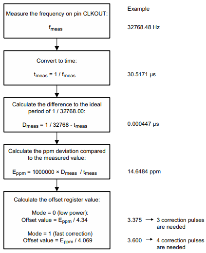
I do not have an oscilloscope with a high enough resolution to accurately measure the frequency for step 1. Is it possible to calculate the offset without one? The NXP application note discussing improved timekeeping has some useful tidbits beyond what was described in the datasheet. Most important is the fact that 1 second of clock drift per day corresponds to an error of 11.57 parts per million. By measuring the drift of the clock over a few days we can do some simple calculations and calibrate the RTC.
RTC offset calculation
| Calculation | Example |
|---|---|
| Record the current time along with how it compares to the clock on the RTC. Wait a few days and do it again. | 22:21 on Jul 18 RTC is behind actual time by 7 seconds 19:11 on Jul 21 RTC is ahead of actual time by 18 seconds |
| Calculate the time between your two measurements in days | 3 days - 3 hours, 10 minutes = 247800 seconds |
| Calculate the amount of drift between your two measurements | 7 s + 18 s = 25 s |
| Calculate the amount of drift per day in ppm | 25 / 24788 = 100.89e-6 = 100.89 ppm |
| Use the value from the datasheet to calculate the offset register value | 100.89 / 4.34 = 23.247 => 23 correction pulses |
What does “correction pulse” mean? The RTC will extend or reduce the amount of time required to consider that a second has elapsed. This is the value that gets placed in the first (least significant) 7 bits of the offset register.
- If your clock is running fast you need to write a positive value to the register. This increases the number of oscillations required for a second to elapse, thereby slowing down the clock.
- If your clock is running slow you need to write a negative value to the register, coded in two’s complement. This reduces the number of oscillations required for a second to elapse, thereby speeding up the clock.
Writing to the offset register
Since the 8th bit of the register contains the mode flag, determining the final byte that should be written to the offset register requires some bit manipulation. I’ve added a calculate method to the RTClib Arduino library that does this for you. The calibrate function can be called like this:
// Adjust for the RTC running fast
#define OFFSET 23

rtc.calibrate(PCF8523_TwoHours, OFFSET);
4 Comments
Thanks! This explains better how to use the calibrate example in the Adafruit Library
Hi! Nice post! I have a few remarks:
1. You wrote: “1 second of clock drift per day corresponds to an error of 11.57 parts per million for a 32.768 kHz oscillator.” You can drop the last part of the sentence: one second of drift per day is 11.57 ppm irrespective of the frequency of the oscillator.
2. The drift rate is easier to calculate if everything is in seconds:
3 days – 3 hours, 10 minutes = 247800 s
drift rate = 25 s / 247800 s = 100.89e-6 = 100.89 ppm
3. A 100 ppm drift rate seems unreasonably high for an RTC. The Adafruit product page states that it “may lose or gain up to 2 seconds a day”, which would be up to 23.14 ppm.
I’ve updated the post with your suggestions, thank you! I agree that 100 ppm drift rate is high for a RTC. I must have been unlucky with this one.
I think adafruit is wrong. This is the second is the second source i find for the clock to be +8 seconds/day (https://www.hackster.io/M-V-P/bring-a-pcf8523-rtc-to-top-accuracy-21a2fd). And guess what: mine is also 8 secs too fast….