How to design and build a breakout board for an SMD component
As electronic components become ever more integrated and miniaturized, it can sometimes be impossible to find a through-hole counterpart to an interesting SMD part. For example, I wanted to do some prototyping with the ZXSC30 LED Driver but it’s available only in a SOT23 package. With some attention to detail and the right equipment, it’s not difficult to design and build your own breakout board for such a component.
Equipment
1. Design the Circuit
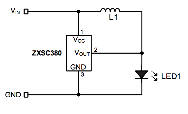
If you scan through the datasheet you’ll often find that this step is done for you, or nearly so. Look for a diagram called something like “Typical application circuit.” It is nice to include required passive components on the breakout board to make it as “plug and play” as possible. In this case, the only external component required beside the LED itself is a small inductor.
Load up a PCB design app like Eagle and re-create the circuit there.
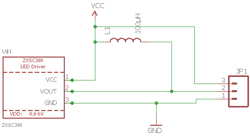
The Eagle design files for this breakout board are available on GitHub.
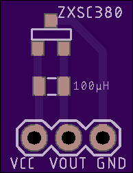
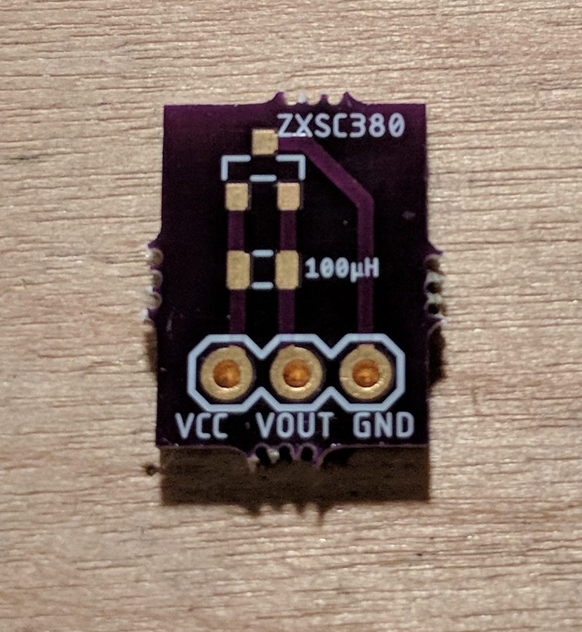
2. Print the Circuit Boards
Oshpark is a circuit board printing service that is perfect for hobbyists. Create an account, upload your Eagle files, complete the purchase and you can expect to have perfect purple PCBs in your hand in a couple weeks. I’ve shared my board design in case you’d like to use it.
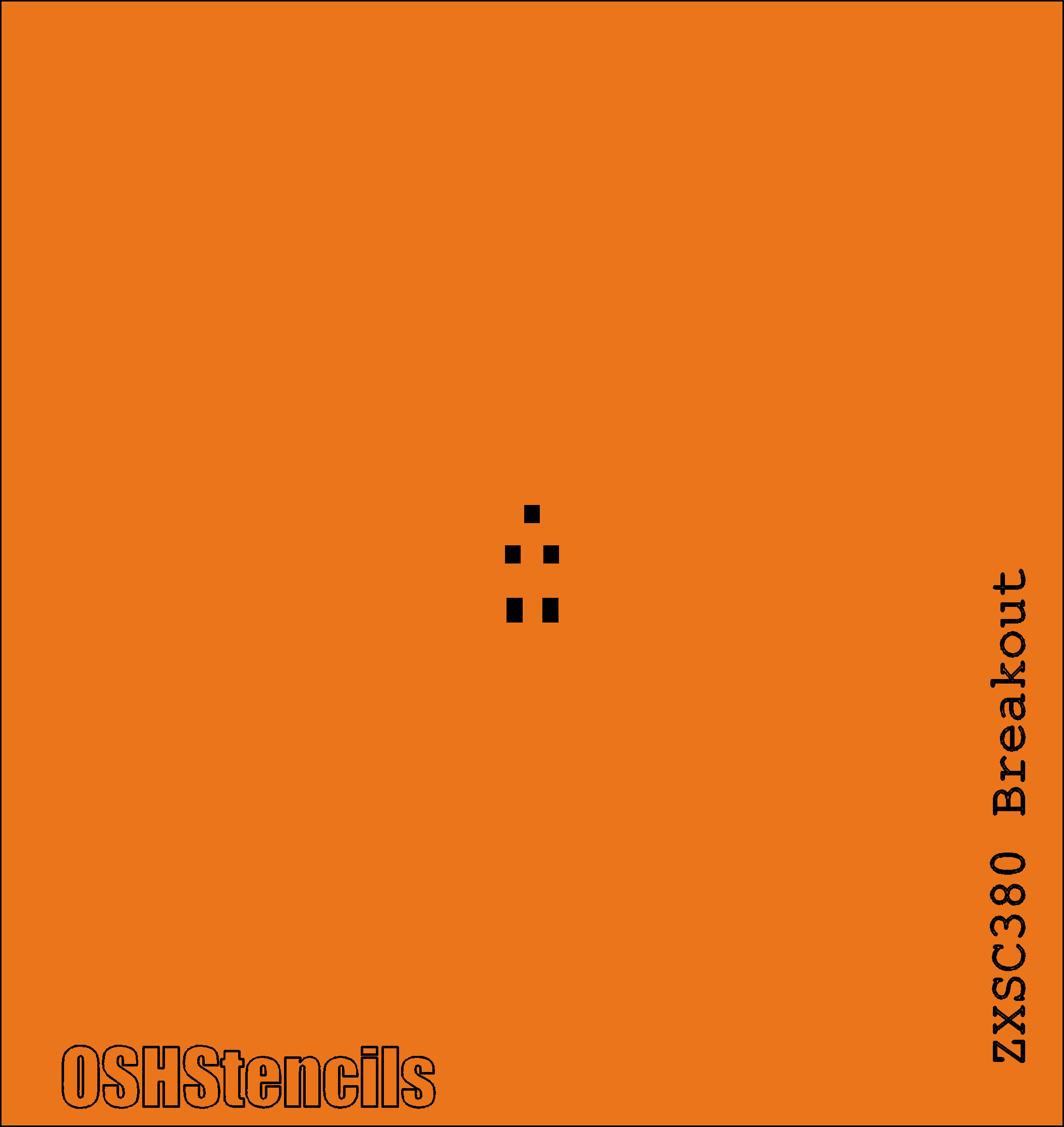
3. Create a Solder Paste Stencil
OSH Stencils is a great service to create a solder paste stencil. Again, create an account and upload your Eagle file. OSH Stencils will use the solder mask layer of your board design to fabricate a polyimide or stainless steel stencil perfectly matching your PCB.
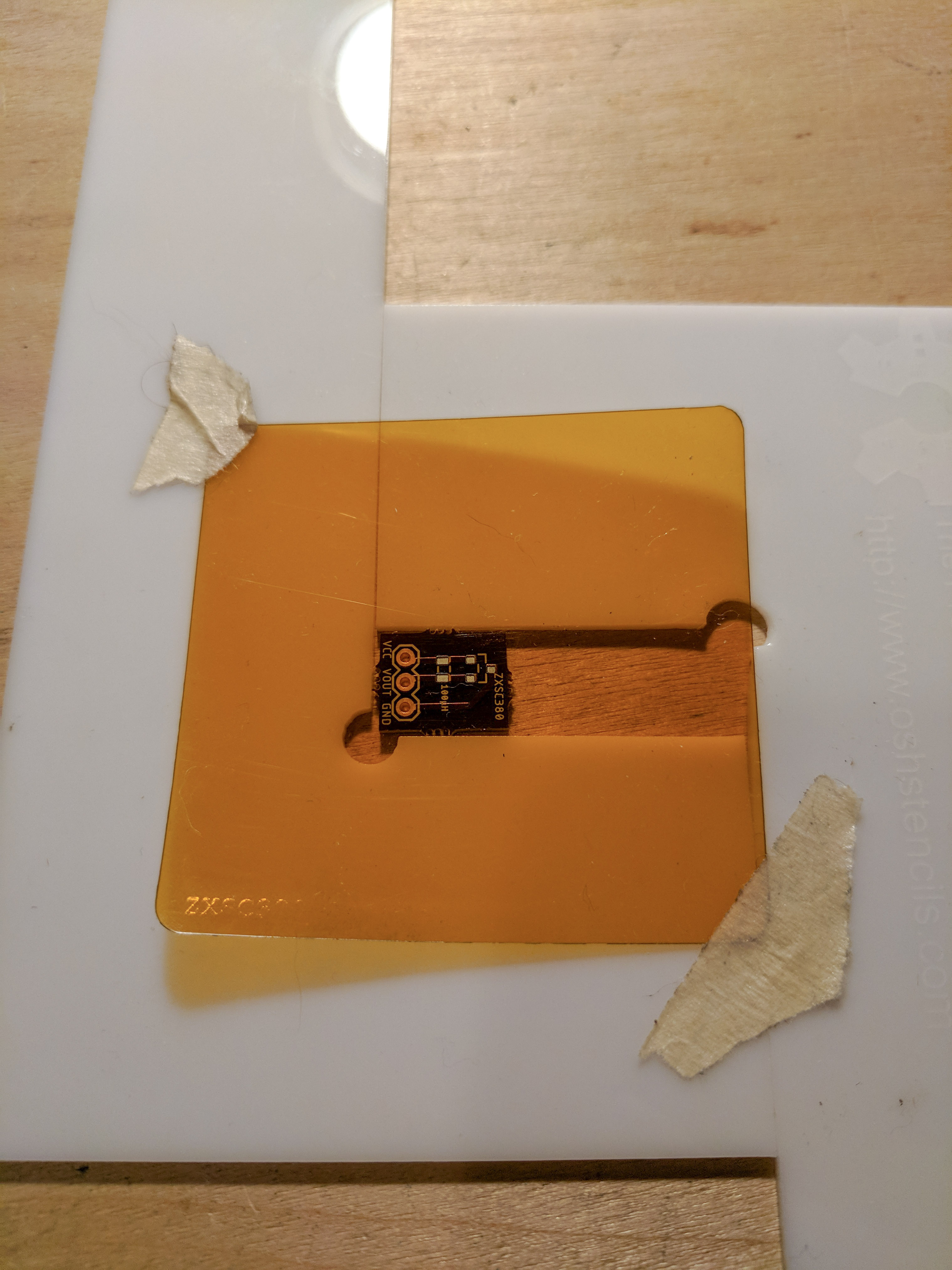
3. Assemble the Board
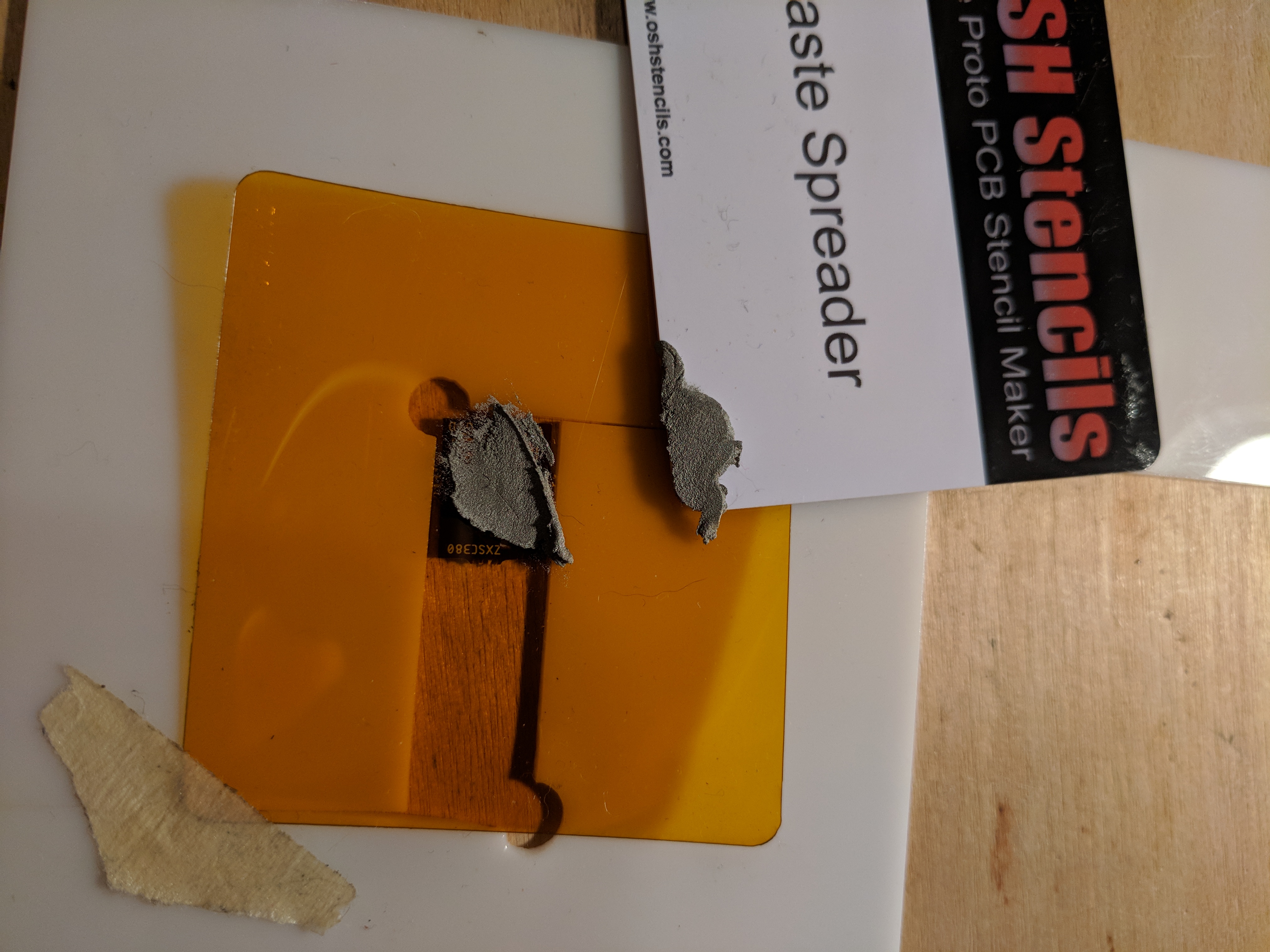
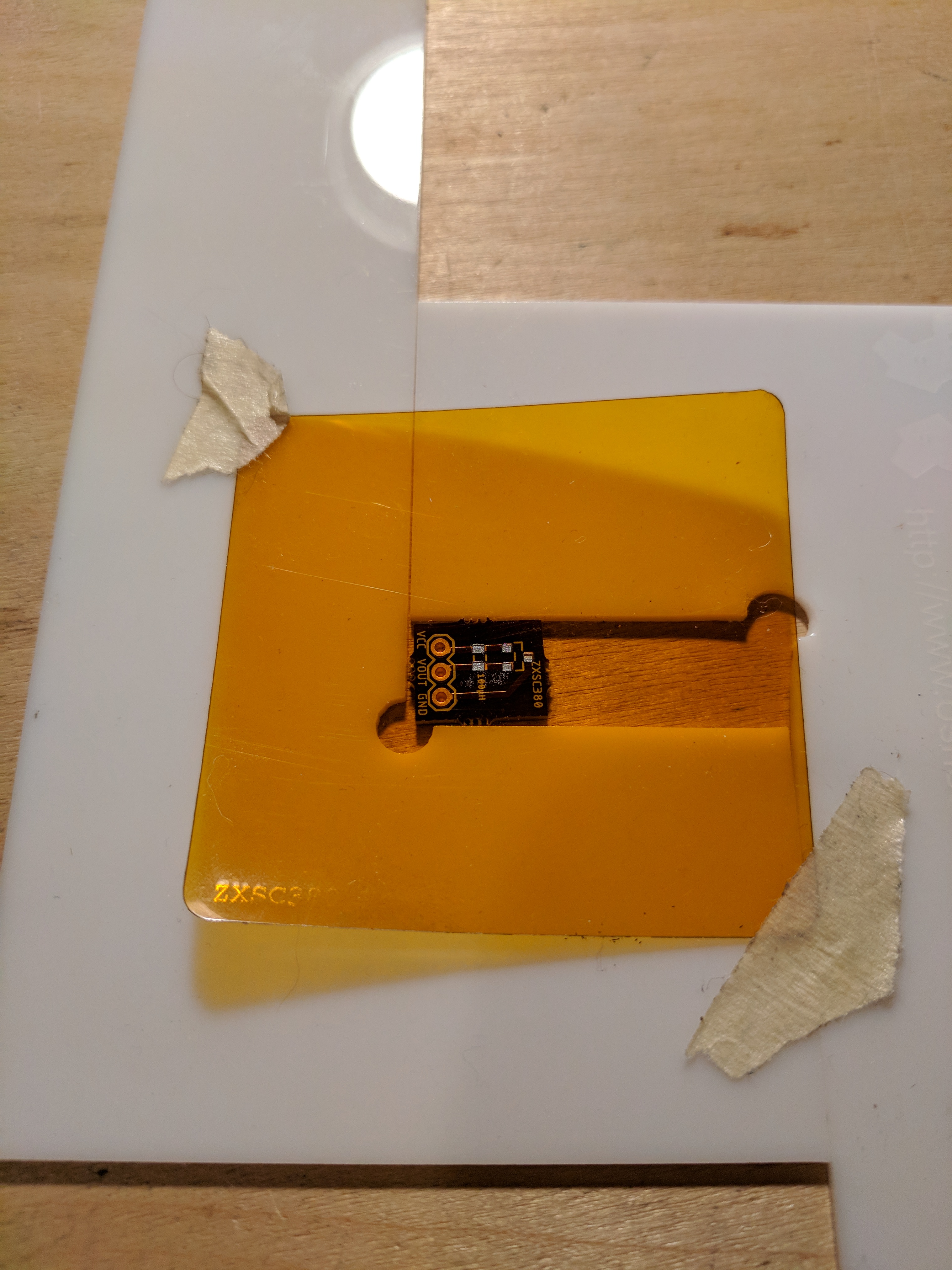
Scoop up some solder paste using the squeegee provided by OSH Stencils and spread it over the aligned stencil. Then scrape over the board using an edge to force paste through the stencil. Scrape the extra solder paste back into its jar and carefully remove the stencil. If the solder isn’t lined up the way you hoped, clean it off with an alcohol wipe and try again.
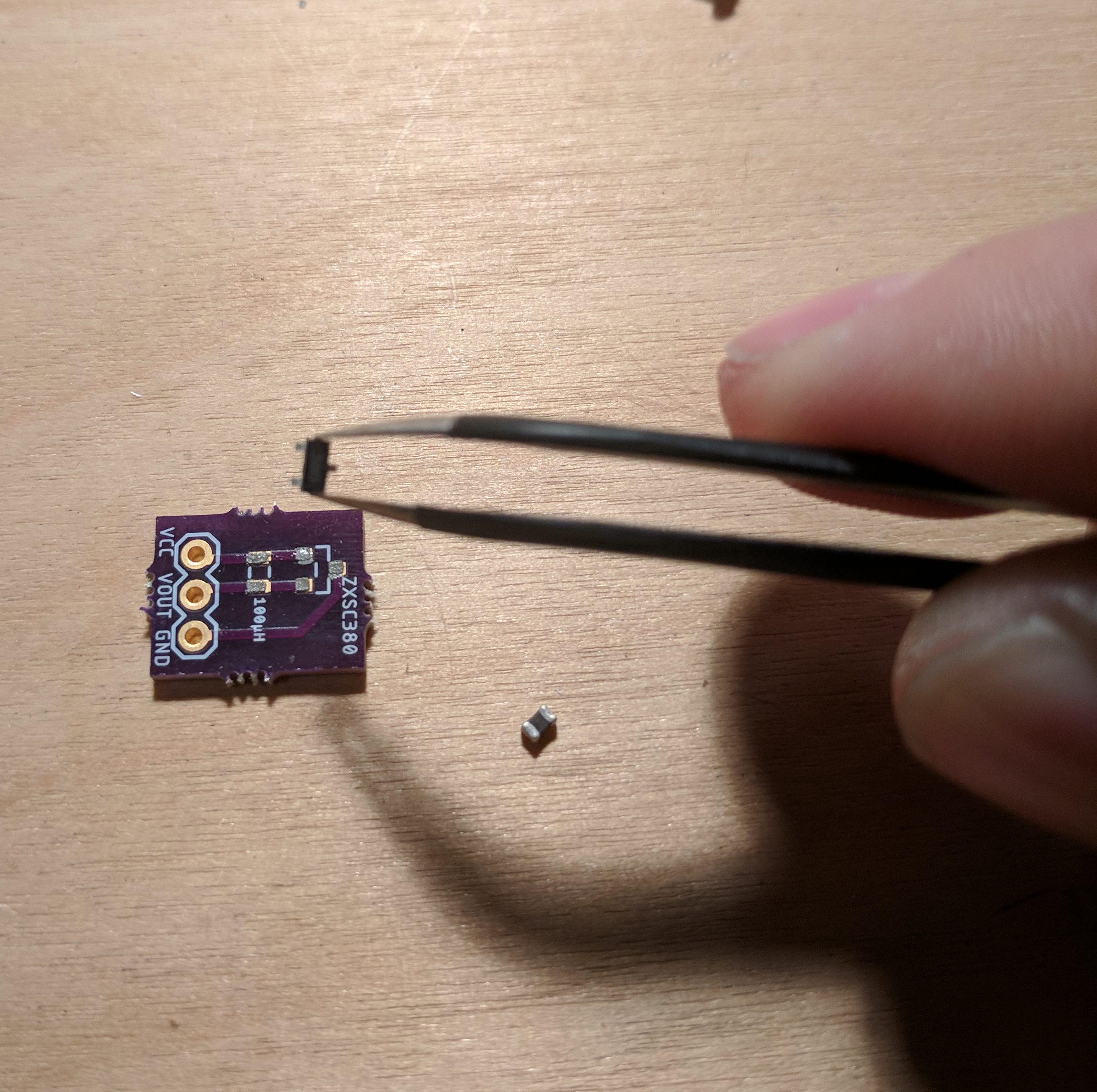
Use fine point tweezers to place the components. The pads should be somewhat aligned but do not need to be perfect. This is because once the solder liquefies, the surface tension tends to pull the component into place.
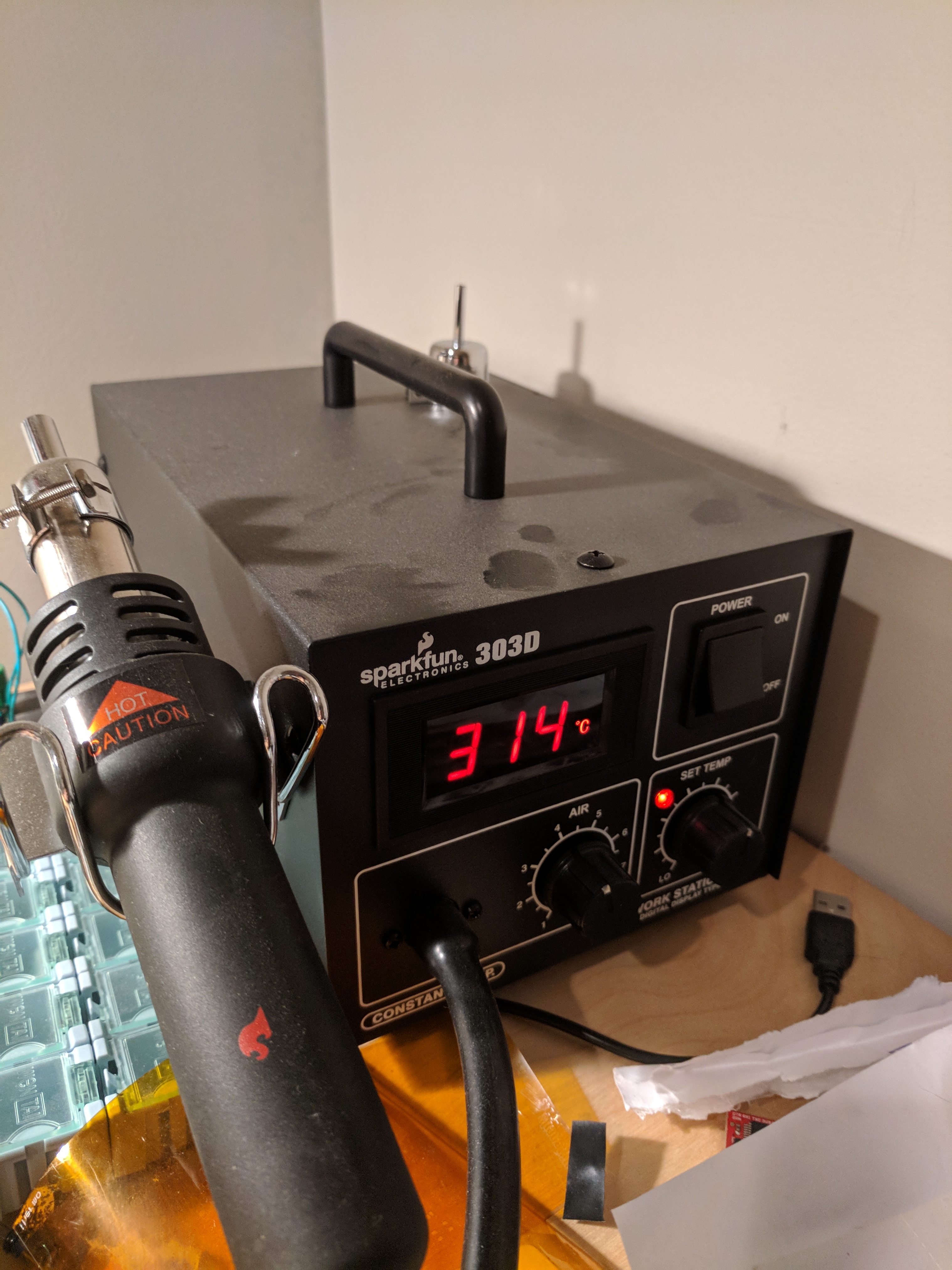
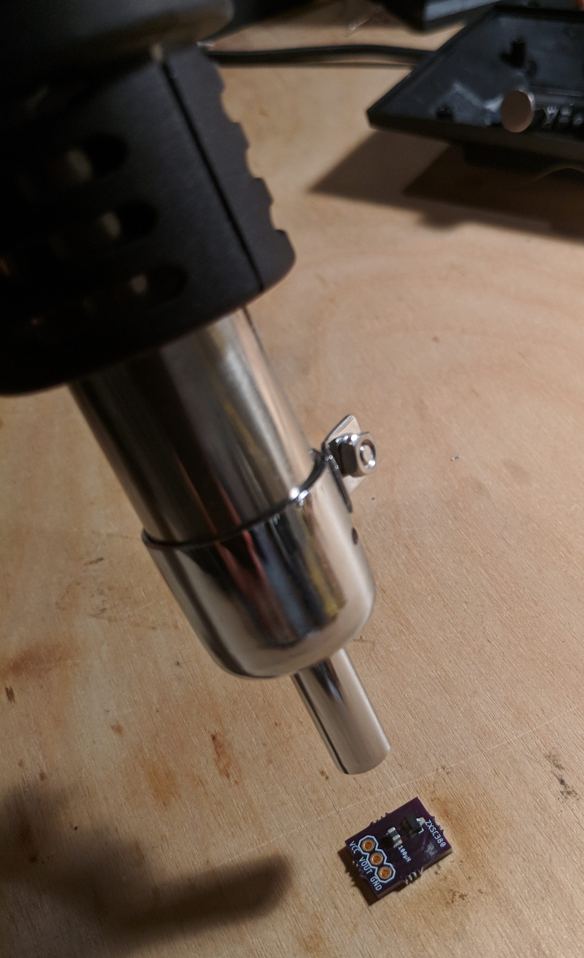
Turn on the hot air rework station and allow it to heat up. Then move the nozzle over the PCB until the solder liquefies. Probably don’t do this on your wood table top =P
4. Test
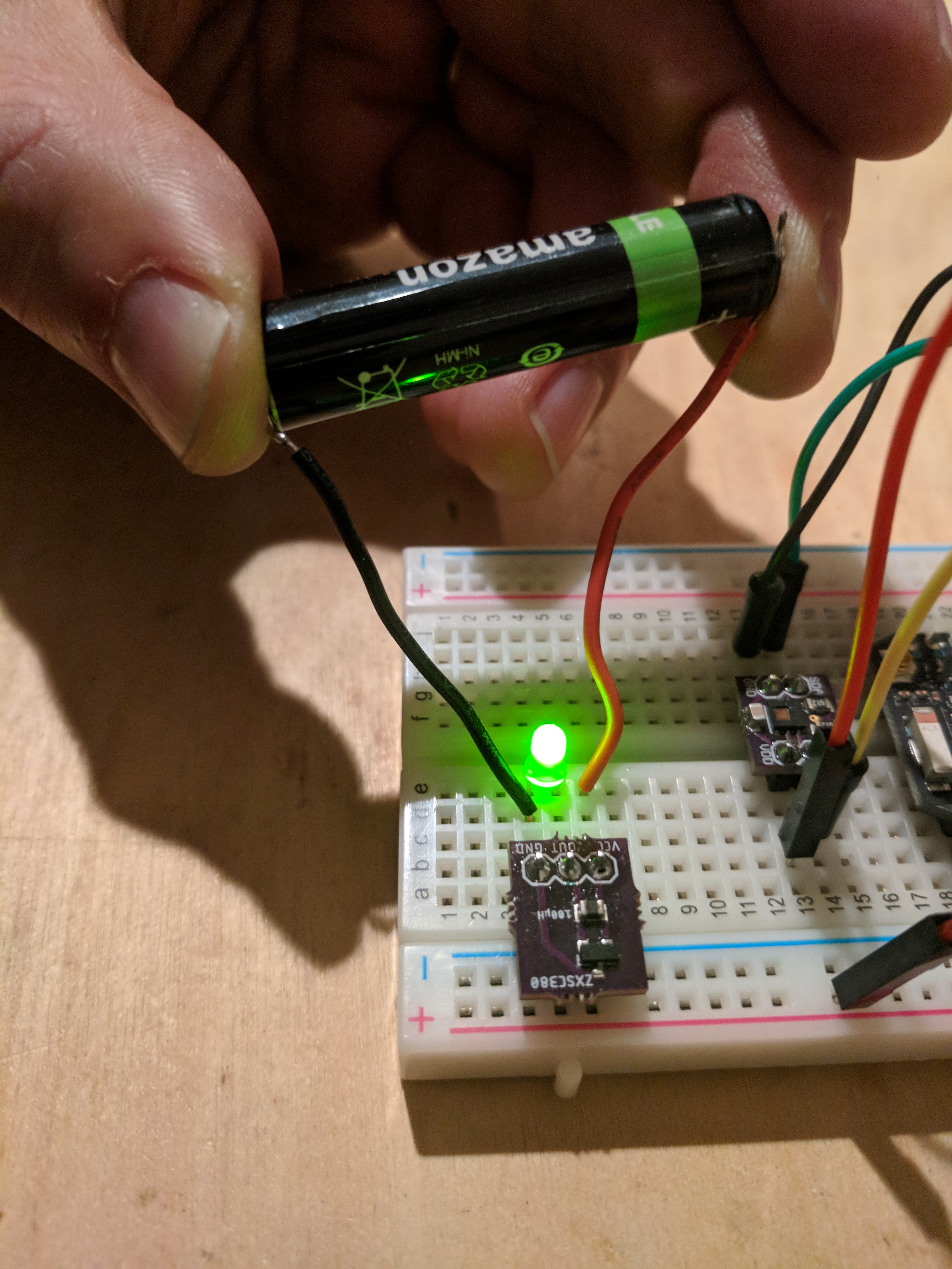
Create a simple test circuit for your PCB to make sure it works. In this case I connect a AA battery to VCC/GND and an LED to VOUT/GND. A single AA battery does not have enough voltage to power an LED on its own but with the ZXSC380, the LED lights up brightly. Neato!
No Comments